You bought new batteries. You fixed the Lidar motor. Your Neato XV looks ready to conquer the world. You slide it onto the charging dock, expecting that satisfying chirp.
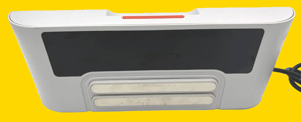
Instead, you are greeted by a Neato charging station blinking green (or sometimes orange) rapidly. The robot wakes up, tries to charge for 3 seconds, and then backs off the dock in confusion. Or worse, the dock is completely dead.
Before you spend $50 on a used charging station on eBay, stop. The problem is likely caused by two tiny components worth about 50 cents each. This guide covers the definitive Neato C10 capacitor replacement, the ultimate badge of honor for the DIY repair enthusiast.
Table of contents
The Symptom: The “Blinking Light of Death”
The Neato XV charging station (Model 14544 / 910-0069) has a known design flaw. The power supply circuit uses electrolytic capacitors that were slightly underrated for the heat they endure. Over 10+ years, these capacitors “dry out” or bulge.
When they fail, the dock can't provide a steady 24V current. The robot senses this “dirty” power, thinks the dock is faulty, and refuses to charge to protect itself. This is often the hidden cause behind a Neato XV-21 not charging or the cryptic Neato Error 0002 (Battery Issue).
Signs your Capacitors are bad:
- The dock light is blinking fast (green/amber) even when the robot is not docked.
- The robot says “My Battery is Low” immediately after docking.
- The robot repeatedly drives onto the dock, wiggles, and drives off.
Neato C10 Capacitor Replacement: Upgrade, Don't Just Replace
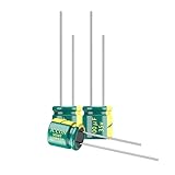
The original capacitors at fault are usually rated at 25V 100µF.
Because the charging voltage is very close to 24V, these 25V caps are running at their limit. We aren't just going to replace them; we are going to perform a robust Neato XV power supply repair by upgrading them so this never happens again.
The Shopping List:
- Two (2) Electrolytic Capacitors.
- Capacitance: 100µF
- Voltage: 35V or 50V (Higher voltage makes them more durable).
- Type: Low ESR (Preferred for power supplies) and 105°C temperature rated.
- Search Term: “100uF 35V Electrolytic Capacitor Low ESR“
- Tools:
- Soldering Iron & Solder.
- Desoldering Pump (Solder Sucker) or Wick.
- Torx T10 Screwdriver.

Safety Warning: High Voltage ⚡
UNPLUG THE DOCK. UNPLUG THE DOCK. UNPLUG THE DOCK.
Seriously. You are opening a power supply that connects to mains electricity (110V/220V).
Once unplugged, press the robot against the charging contacts for 5 seconds to discharge any remaining energy.
Do not touch the large transformer coils or the large primary capacitor (the big one) on the board. We are only working on the low-voltage output side.
The Surgery: Step-by-Step
Step 1: Open the Case
Flip the charging base over. There are usually 4 screws hidden under the rubber foot pads. Peel back the pads (you can glue them back later) and remove the screws with your T10 driver.
Carefully separate the top and bottom shell. You will see the main circuit board.
Step 2: Locate the Culprits (C10 and C13)
Look at the circuit board. You are looking for two small cylindrical towers labeled C10 and (sometimes) C13 printed on the green board next to them. They are located near the heavy cables that go to the charging strips.
- Visual Check: Look at the tops of these cylinders. Are they domed or bulging outward? Is there brown crust leaking from the bottom? That is a confirmed kill. Even if they look flat, they are likely dried out inside.
Step 3: Desolder the Old Caps
- Flip the board over to access the solder joints.
- Locate the two pins corresponding to the C10 capacitor.
- Heat the joint with your iron and use your solder sucker to remove the old lead.
- Gently wiggle the capacitor out.
- Repeat for C13 if you are replacing both (Recommended).
Step 4: Install the Upgrades (Polarity Matters!)
This is critical. Electrolytic capacitors have a Positive (+) and Negative (-) side.
- The Capacitor: The negative side has a big stripe (usually white/grey) with minus signs on it.
- The Board: The circle printed on the board has a shaded half (Negative) and an unshaded half (Positive). Note: Double-check this! On some Neato revisions, the shaded part is negative, but always look for the
+sign if printed.
Insert the new 35V capacitor. Solder the legs. Snip off the excess wire.
Step 5: Test Before Closing
- Place the board back into the bottom shell.
- Plug the power cable into the wall (Be careful not to touch the board!).
- Does the LED light turn solid (or shut off if no robot is present) without rapid flickering?
- Unplug, reassemble the case, and screw it.
The Result
Slide your Neato XV-21 up to the contacts. Watch the LCD screen.
If you see the battery icon start to “fill up” with a pulsing amber light, you did it. You just performed board-level electronics repair and saved a piece of hardware that 99% of people would have thrown in the trash.
Do you need help to Neato charging station blinking green?
If you have questions about replacing the capacitor to fix Neato charging station issues, please let us know in the comment box below.